Overview

This blog is intended to document the build of my Gardner Douglas Mk4 Cobra; partly as IVA evidence, bit primarily to help others learn from my mistakes and/or successes.

I will endeavour to post as often as possible, with a view to entering a single post for a particular element of the build process, however inevitably some things may not be completed in one go. All posts will be tagged so it should be easy enough to find the information you seek.

Please subscribe to receive emailed updates and feel free to post any comments or questions which I will make my best efforts to respond to.

Monday 13 November 2017

Uprights & Hubs

Front uprights, bearings and hubs
Normally these come pre assembled by GD, however they were having problems with their hydraulic press so it presented an extra step for me to contend with.  First the outer races of the taper roller bearings need pressing in to the hubs, as I don't have a press ended up outsourcing this to a local HGV workshop.  Now the bearings can be packed with the supplied grease before being laid into the outer races within the hubs; the outer bearing is held in place with a seal cup which is gently tapped in to place with mallet and copper drift.  The inner bearing has an alloy cap instead of a seal.

Once the bearings are in place, the hub can be pushed through from the outside and held in place with a heavy duty washer and nyloc nut, this is a close tolerance fit so I placed the hubs in the freezer overnight to ensure they slid through nicely.  Whilst both uprights are identical one of the hubs has a left hand thread, this needs to go on the left side of the car to avoid undoing in motion.

View from inboard side after hub pushed through

View from inboard side showing heavy washer and hub nut (LH threaded nut on front LH side of car).  An alloy dust cover taps on after the nut is torqued up.

Torqueing up front hub nut

The hub also has some tapered stainless steel sleeves that need pressing in for the ball joints, these have a top hat and can just about be pressed in using a bench vice.  Again, I put these in the freezer overnight to help.

Rear uprights, bearings and hubs

The bearings for the rear uprights are much the same as the fronts but are slightly larger diameter and have a seal on both inboard and outboard sides.  Again the outer races were pressed in by the HGV workshop and the rest assembled as per the front ones.

The hubs differ from the fronts in that they have a splined centre which accepts a corresponding inner hub for the drive shaft.  Again the 'frozen' outer hub is installed first, the inner hub then slides into the splines before the washer and nut are installed.  This time the LH thread goes on the RH side.

 Inboard rear hub showing bearing and grease seal in place

View from outboard showing bearing prior to insertion of oil seal

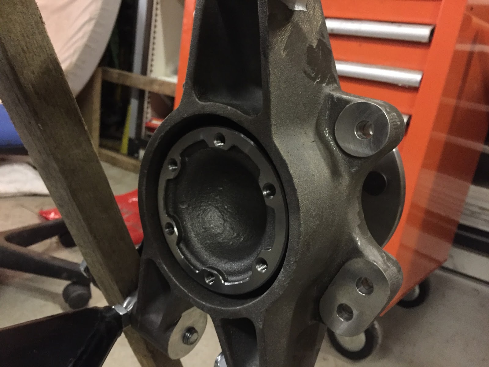
View from inboard showing inner hub flange for driveshaft

View from outboard showing hub, washer and nut.  (LH thread nut on rear RH hub)

Front wheel studs
The wheel studs would also normally be pressed in by GD, however I only the rears had been.  I tried using the vice but couldn't get enough pressure so resorted to pulling the studs through from the outside.  Each stud was greased and pushed through the hole, I then used a stack of washers and high tensile nut to draw the stud through in to the hub whilst holding the hub still with some unistrut bar.  This was repeated another 9 times and hey presto, something to bolt the wheels to.

Washers and nut used to pull stud in to place.  I started using an old wheel nut but that destroyed the washers so I moved to a high tensile hex nut which worked much better.

Differential

The BTR differential comes filled with oil and is very heavy so having a friend on hand was extremely helpful, doing it on my own would have been a real struggle.  The diff was lifted in to place and placed on my friends knees whilst he sat on an old office chair, this kept it roughly in place and allowed me to get a couple of bolts in to relieve the strain.

Mounting is straightforward with 3 bolts in the front, 4 to attached to the angle bracket and 2 bolts with nuts to hold the bracket to the chassis.  Once all the bolts are in loosely they were tightened up permanently.  Whilst this all sounds a five minute job, it took two of us almost an hour!

 Rear of diff showing angle bracket

Front of diff showing input flange

Saturday 2 September 2017

Rigid Brake LInes

The rigid brake pipes come coiled as a kit already flared with the fittings installed, these were uncoiled and straightened by stretching them between myself and a friend.  The shorter of the two is for the front and the longer is for the rear, the kit also comes with a couple of 'T' pieces and the flexible hoses for each brake.

Front brakes
The 'T' piece was loosely bolted to the pre-installed rivnut adjacent to the lower diagonal brace mount, this was tightened fully once the pipework was complete.  Starting at the front a handheld pipe bender, I created the first bend then offered it up to make sure it was right before continuing with the next.  This process was repeated until all the bends were complete.

The pipe route is shown in the pictures below:
From 'T' piece, along lower frame and under engine mount...

...continues along lower frame then up round tube to aluminium block.

The flexible hoses are different lengths, the short one goes right and the long one goes left

Rear Brakes
The rear 'T' piece is bolted in the centre under the frame above the front diff mount, the rivnut here was a little loose so I tightened it with a spare bolt and a couple of nuts.  I used the same process of offer up, mark, bend, check, move on as I did for the front pipe, starting at 'T' piece and moving towards the alloy block.

Two shorter rigid pipes go from the 'T' piece to some brackets where they meet the flexible hoses.  The brame was drilled and tapped for the 'P' clips.

The pipe route is shown in the pictures below:

From 'T' piece along right hand upper frame rail...


...up frame rail above gearbox...

...final right angle to alloy block.

Right hand side from 'T' piece to flexible hose bracket

Left hand side from 'T' piece loops under fuel pipe, functional but not pretty, will redo this!

Fuel lines pt1

Fuel Line
The fuel line is the bigger diameter pipe in the kit and comes coiled up with a 90 degree bend at one end, this bend goes at the front.  I carefully uncoiled the pipe, you can buy pipe straighteners but I found pulling on one end whilst a friend holds the other does the job perfectly well.

The pipe runs along the left hand top chassis rail to just behind the body mount, then dips down slightly to avoid the handbrake cables, over the front diff mount before doing an 'S' bend outboard and over the driveshaft.  I drilled and tapped the frame to secure the pipe with 'P' clips, adding a little grease in the holes to hopefully stop corrosion.

90 degree bend approximately 25mm in front of cross member

Routed along right left hand top chassis rail...

...slight downward bend rear of body mount...
...over front diff mounting plate...


...'S' bend outboard and over left hand driveshaft.

Chassis Collection

I was hoping to use the August bank holiday weekend to assembly as much of the chassis, thankfully GD had it ready for collection on the 23rd so I booked the day off work.  I have a double garage but with shelving all down one side and other equipment down the other, it would have been a squeeze with both the body and chassis in there. I didn't want to just leave it outside so I had to think outside the box.

Old 4 man tunnel tent is a perfect fit for a Cobra!
With the garage clear I set off to Grantham, roof bars fitted and trailer in tow.  I had previously dropped of my engine/gearbox at the open day in May as GD needed it to fabricate the engine mounts, so that would go in the trailer, the chassis on the roof and the many boxes of other bits filled the boot.

Chassis is only about 75kg so easily goes on the roof (didn't do much for my fuel economy though!)

Thankfully I have a large estate car
The first task on the list when I got it home was to lay everything out and identify what goes where and with what etc.  It turned out there were a few bits missing but a quick email to GD has those in the post.
Front suspension components

Rear suspension components

Monday 5 June 2017

Side Repeaters

I had been putting off the side repeaters as I couldn't decide which ones to fit until seeing some LED ones on the GD stand at Stoneleigh. They come with a black rubber grommet and optional chrome surround and I managed to pick them up at the show from CBS.

Fitting these is very straightforward once you've decided where you want them. Some people place them towards the rear above the louvres but I chose to put mine further forward.

I placed 25mm wide masking tape along the top and forward edges of the louvre opening, then another strip above and one behind. Where the tapes overlap creates a diamond shape above and inline with the forward edge of the opening.

Drawing a cross to join the opposing corners of this diamond gave me a centre point to drill a 20mm hole. Once the edges are cleaning up the side repeater just pushes in. I've order some two pin Econoseal plugs which I'll install later.

Repeat for the other side, all in about 20 mins work.

Taped up and centre point marked

Side repeater fitted

Stop switch

I had forgotten to install the brake light switch when I installed the pedal box, so that was removed again. Not an easy job on your own unless you have 'go go gadget arms'!

As I'm using the Lexus engine and intend to utilise the cruise control, I kept the swith from the donor. This switch has 4 wires, two for the brake lights and the other two for the cruise control.

I created a small bracket out of 25mm x 2mm flat aluminium bar with a slight bend in the middle to position the switch at the correct angle. I then drilled and tapped the pedal box and bolted it on with M5 button heads and spring washers.

I've also installed a second switch on the clutch pedal which will stop the starter operating unless the clutch is depressed, thus never accidentally starting it in gear.

1 of 2 brackets made

Clutch switch fitted 

Clutch and brake switches fitted

Needed a clean!

My wife and I have recently had a baby so the last few months have seen little progress, however this weekend they both went away which gave me a chance to reacquaint myself with the car.

It had gathered a lot of dust and grime over time so the first order of the day was to give it a good clean.

Before... 
After.
I forgot how good it looks in sunlight. 

Windscreen Reassembly

I've had the windscreen frame back from the powder coaters for months now, but have been putting of reassembling it, until now.

The glass has been shifted around the garage wrapped in an old duvet and it's only a matter of time before it gets broken, so I decided it was about time to refit it in the frame.

This was not a task I was looking forward to, and that trepidation was for good reason. Unfortunately; due to my intense concentration, I forgot to take any pictures of the process but the general idea is this:

1. Refit the lower frame first
2. Start in the centre and work outwards gradually 
3. Use washing up liquid liberally between the seal and frame
4. Take your time. I ended up doing it three or four times before getting it right
5. Find something soft to work on. I used an old foam mattress

There are two main challenges, the first being the fact that the frame and glass aren't exactly the same shape so careful manipulation is necessary.

The second; and most frustrating, is that the seal isn't a 'U' shape buy instead it is flat. This means that you need to simultaneously fold it over the glass, press it in to the frame and stretch is slightly so the corners meet. All this whilst trying not to break the glass and being covered in washing up liquid!

Ideally a second pair of hands would be useful, however after much cursing and nervous sweating I eventually managed to piece it all together without major incident.

I think it looks great along with all the other matte black 'chrome'

Wednesday 31 May 2017

Inspiration

I've actually had two Cobra builds underway, one a GD and the other a lesser known Fujimi RS-5 427.  The latter is generally a quicker build and only took a couple of months!

Engine Update 5

Now that the engine and gearbox have been coupled together it was time to deliver it to GD, they need it in order to fabricate the mounts for the chassis.

The 20th May was the GD open day at their new premises in Grantham so I seized the opportunity and loaded the powertrain in to a borrowed trailer and headed up.

It was a great turnout and fabulous day despite the heavy downpours and the engine was unloaded without issue. I was pleasantly surprised to find most people very interested in my choices rather than the shunning I was expecting for not using an American V8!

I still have to reconnect the loom to the various ECU plugs but that can be done when I get it back along with the chassis, hopefully in a couple of months.

It was also great to meet a few new people, some of which I had already chatted with online but great to put a face to a name. 

Engine & Gearbox loaded up in an old trailer tent

And below a few of the cars at the open day

Stunning car finished with LS7,  black chrome and lovely interior 

The GD racer

Nice to see another orange beast and the best use of a fishing umbrella I can think of. This is added to my shopping list

Friday 10 March 2017

Engine Update 4

So I finally received my adapter plate & pilot bearing reducing sleeve (SWR Motorsport) and clutch & flywheel (TTV Racing) so I could bolt the two together.

I had trouble getting accurate readings while clocking the bellhousing however the gearbox did slide on easily. Even though, I've ordered another DTI so will likely do it again just to be sure.

There's a lot of bolt on, bolt off activity to set this all up but I got there eventually. The bearing sleeve was used as the TKO pilot bush was too small for the 1UZ crankshaft, it's a tight fit so was put in the freezer the night before and then fitted with a dab of Loctite 272 in to the end of the crank. The pilot bush just slots inside this.

Next the flywheel was bolted on with new ARP bolts and torqued up as per ARPs instructions. The clutch pressure plate, bell housing and adapter plate were temporarily installed so I could measure the distance from the gearbox mating face to the pressure plate fingers. This measurement was then used to set the adjustment of the Tilton hydraulic release bearing.

Next the bellhousing came of, pressure plate removed and bellhousing refitted complete with adapter so I could clock it in. The opening in the adapter is quite small so I struggled to get the DTI lined up properly so I will probably have to repeat this step once I get a different DTI.

With the bellhousing back off again I could assemble and align the clutch. My alignment tool needed a few wraps of tape to get the right fit but was pretty straightforward.

The bellhousing was then bolted to the gearbox and the clutch release was slid over the input shaft bearing retainer. This release bearing requires one of the bearing retainer bolts to be replaced with a pin which stop the bearing from spinning. The release bearing position can be adjust by screwing it in or out on its own sleeve. There are two hoses which need to exit the bellhousing so holes were drilled foe these, although they may have ended up too close to the exhaust!

With a bit of graphite grease applied to the splines, I could now mate the engine and gearbox together. The engine was on the hoist and the gearbox on its stand (old office chair) so a sexond pair of hands was needed to keep everything steady but it all slid together remarkably easily.

I will be taking the assembly up to GD at the beginning of April so they can make up the engine mounts with a view to hopefully picking up the chassis at the GD open day on 20th May, fingers crossed. 

Shiny adapter plate and bearing sleeve 

Sleeve and bearing partially installed 

Sleeve and bearing pushed home

Flywheel installed

Clutch assembled 

Release bearing installed