Overview

This blog is intended to document the build of my Gardner Douglas Mk4 Cobra; partly as IVA evidence, bit primarily to help others learn from my mistakes and/or successes.

I will endeavour to post as often as possible, with a view to entering a single post for a particular element of the build process, however inevitably some things may not be completed in one go. All posts will be tagged so it should be easy enough to find the information you seek.

Please subscribe to receive emailed updates and feel free to post any comments or questions which I will make my best efforts to respond to.
Showing posts with label pedals. Show all posts

Monday, 5 June 2017

Stop switch

I had forgotten to install the brake light switch when I installed the pedal box, so that was removed again. Not an easy job on your own unless you have 'go go gadget arms'!

As I'm using the Lexus engine and intend to utilise the cruise control, I kept the swith from the donor. This switch has 4 wires, two for the brake lights and the other two for the cruise control.

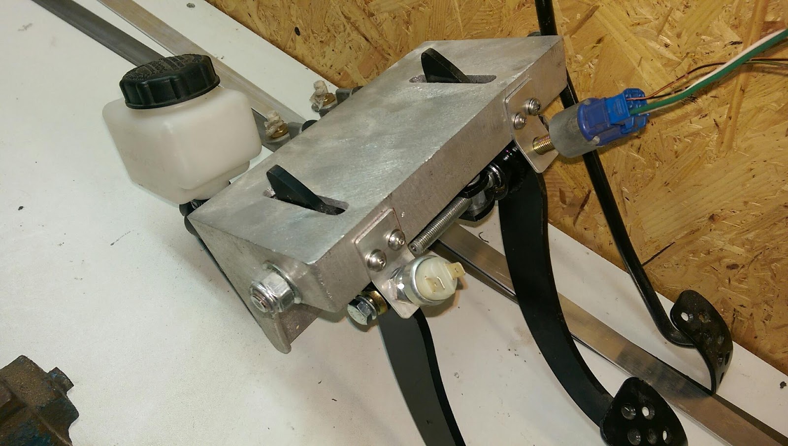
I created a small bracket out of 25mm x 2mm flat aluminium bar with a slight bend in the middle to position the switch at the correct angle. I then drilled and tapped the pedal box and bolted it on with M5 button heads and spring washers.

I've also installed a second switch on the clutch pedal which will stop the starter operating unless the clutch is depressed, thus never accidentally starting it in gear.

1 of 2 brackets made

Clutch switch fitted 

Clutch and brake switches fitted

Thursday, 7 April 2016

Accelerator pedal

The GM LS wiring loom I have comes with an electronic accelerator pedal but there isn't enough room to install it next to the pedal box so some creativity had to happen.

Andy from GD had mentioned something about mounting it on the other side and connecting it to the accelerator. I first cut the pedal off ensuring I left as much of the lever arm on as would fit within the wheel arch compartment to give the most amount of travel. I also had to modify the shape of it to allow the clevis to fit. It was then offered up, the holes marked and drilled in the bulkhead.

To remove the accelerator pedal I had to loosen all the pedal box mounting bolts which is easier said than done, but I manged it but putting one are through the footwell extension hole. Once removed a filed a couple of flats on the end pedal arm and drilled a 6.5mm hole for the clevis pin. The pedal was bolted back on but the 20mm hole I had drilled in the bulkhead for the turnbuckle wasn't quite right so this was extended down.

The turnbuckle I had was a little short so it was extended with some M6 threaded stainless rod an extension nut. It was then connected and adjusted so the accelerator pedal is the same height as the others.

I haven't ended up with quite as much travel as I'd hoped so I may have to move the turnbuckle fixing down the pedal arm later.

Modified GM accelerator pedal 

Modified GD accelerator pedal 

Turnbuckle connected in footwell 

Modified GM pedal in wheel arch compartment, thete is still plenty of room to get the plug in

Tuesday, 5 April 2016

Pedal Box

The GD manual suggests lining the top of the pedal box up with the lip in the engine bay but I fitted mine about 15mm down, mainly incase my wife ever drives it!

I started by marking a horizontal line with a spirit level where GD recommend then measured down from there. The pedal box was then dissassembled so that I could more easily used the casting to mark the holes. The casting was offered up as far left as possible; making sure enough room was left for the left had nut, and one of lower bolt holes marked.

This first hole was drilled then the casting bolted in place, this allowed any fine tuning of level before the other holes were marked abd drilled. The casting was removed and the remainder of the holes drilled, I didn't have the right size holesaw for the master cylinders so these were cut small and opened out with die grinder.

The pedal box was reassembled and and the brake bias bar installed. I measured between the centres of the master cylinder holes which gave 62mm so the two clevis' were set 62mm apart and equidistant from the pivot. These will be set and locked later,  I'm just not quite sure by who!

Starting with the clutch cylinder the pedal box was bolted in place, the brake cylinders followed. The two brake cylinders are different sizes internally (0.70" and 0.75") so it's worth taking note of which one has been put where.  To get the right pedal height and clearance from the casting about 6mm was trimmed off the end of each brack cylinder thread. I then adjusted the clutch clevis to give a similar position to the brake pedal.

As I'm going to be using an LS engine I will be using the electronic throttle so a modified GM throttle pedal will be installed horizontally on the other side of the bulkhead. I am waiting for the postman to deliver a turnbuckle to finish this but it will mean taking the pedal box off again to drill the brake pedal arm as there's not enough room to get it off in situ.

The manual suggest placing the clutch and brake reservoirs in the engine bay and running hoses down to the master cylinders but to keep the engine bay uncluttered I'll install mine above the master cylinders. The clutch kit comes with two different reservoir sizes and various mounting options, I've placed the smaller one directly on top of the cylinder. I need to make a bracket to fix the brake reservoir to the bulkhead.

GD recommended height of pedal box, mine ended up 15mm lower

Checking level after first two holes drilled

All holes marked reading for drilling 

Pedal box installed

Master cylinders installed 
Safety first! 

Footwell extension

I had my Son down over Easter so it was the perfect time to tackle the pedal box as it needs a second pair of hands (unless you're a descendant of Stretch Armstrong or Gadget Man!).

The first thing to do was cut out the opening for the footwell extension as this will provide additional access. The extension piece was trimmed around the lip which was pre-marked then offered up to the car from inside the engine bay. I drew around it to mark the extremities on fhe body, then measured in the width of the lip (25mm) to mark the cut lines.

I used an air die grinder to cut just inside the line, final filing will be done once the extension is fixed in place. I then marked and drilled 6 holes in the extension and installed M5 rivnuts. These holes were transferred to the body and drilled, the extension will be fitted later with either silicone sealant or a foam/rubber gasket.


Extension taped in position ready for holes to be drilled for rivnuts

Extension from inside, the edges will be filed to match the profile of later