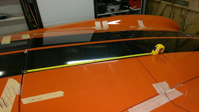
Hi I'm not keen on the agricultural operation and look of the GD supplied boot and bonnet stays so I've decided to go for gas struts.
I have used Dales blog as a basis although I got my struts from WDS Ltd, SDS did do stainless ones but they were twice the price.
Bonnet
I decided to use slightly longer struts than the GD stay, this will provide a bit more leverage hence a lower force is required which will hopefully alleviate the concerns of distortion to the bonnet. Atleast that's the theory!
I ordered adjustable struts with ball end fittings (model 850-0819250) which are about 600mm overall length with a 250mm stroke, the full spec can be seen here. I also ordered some 90 degree brackets with integral ball fittings for the top ends.
I started by propping the bonnet up so that the hinges were a few millimetres from touching the body, I then offered up an extended gas strut so it was just off vertical and marked the mounting points. I now had a mark on the underside of the bonnet which was extended around to the top of the bonnet and another on the inner return of the engine which I transferred out to the wing.
Now with the bonnet shut I could transfer these line across and measure between them. As long as this measurement is more than the compressed length of the strut then everything will close fine.
Using some 3mm aluminium angle I created a strengthening plate to sit behind the return edge. Due to the radius of the return this bracket wouldn't sit flush against both the vertical and horizontal edges so I made some spacers too.
With this clamped in place I marked and drilled the pilot holes, then removed and opened all the holes out. Most are 6mm but for the ball end, I had to thin the GRP to recess it slightly as the thread wasn't long enough. This all then bolts in place and the strut can be connected and with the stainless 'L' bracket connected to the other end the holes can be marked and drill on the bonnet rib. I used 2 M4 rivnuts here.
To ensure that the opposite side was mounted in the same place I had to transfer the mounting point centres to the other side, which is easier said than done due to there being nothing to easily measure from. My method was to tape a bit of string and the known point on the completed side then pull it taught across the bonnet. I then measured between the front of the bonnet and the string along the stripes each side then compared the two. I then adjusted, measured and compared until they matched then marked the othet side.
With the mounting points transferred across I installed the second strut using the same method as the first. Gas was released in 1 second squirts from each strut in stages so they were always equal, until they had enough force to keep the bonnet open without the bodywork flexing when trying to close.


No comments:
Post a Comment